
Optimizing Infill Density for FDM Parts

Infill is a critical property of mechanical components manufactured with Fused Deposition Modeling (FDM, also known as FFF). If you have ever built an FDM part yourself, you probably chose the default setting at first, which is 15%. Or maybe you bumped it to 50% because the part felt too fragile. But did you ever wonder whether the pattern inside the part matters just as much as how much material is there? We did. And we decided to actually test it.
Our team worked with a master's student at Deggendorf Institute of Technology to run a proper, controlled experiment: 200 printed cylinders, three different internal patterns, five density levels, compressed on a lab testing machine until they broke. Here is what we found — and why some of it genuinely surprised us.
What is Infill?
When an FDM 3D printer builds a part, the part is not fully dense. The parts is made out of solid bottom layers, solid walls, solid top layers - and infill for the remaining part volume. This is done to save on build time and weight. Instead, the printer creates a thin outer shell and then fills the inside with a repeating pattern — like a skeleton inside the part.
Infill has two main properties: pattern, and density. Infill density controls how much of that skeleton is filled in — 20 % means mostly air, 100 % means completely solid. Infill pattern controls the shape of the skeleton. And wall loops control how thick the outer shell is. Change any one of these and you change how strong the part is. The question is: which one matters most, and by how much?
We have tested different patterns at varying densities under compressive loads. Continue reading to learn about our results.
Compressive Load Testing
Tested Patterns
We focused on three patterns that are commonly available in slicing software and represent genuinely different internal geometries:
Grid — the criss-cross pattern
Straight lines crossing each other at 90°, forming a regular square lattice. Simple, fast to print, and very well connected internally. When you push down on a part from the top, these grid lines act a bit like little columns — they're aligned with the load and resist it directly.

Rectilinear — parallel lines, alternating layers
Each layer is just straight parallel lines. The next layer runs perpendicular. It's the simplest pattern of the three and prints quickly, but it's also the most directional — it behaves differently depending on which way the load pushes.

Gyroid — the smooth 3D curve
The gyroid is a mathematical surface that curves continuously through three dimensions with no flat sections or sharp corners. It looks complex, it looks fancy, and engineering textbooks often highlight it for its uniform strength in all directions. We expected it to do well. Spoiler: it's complicated.
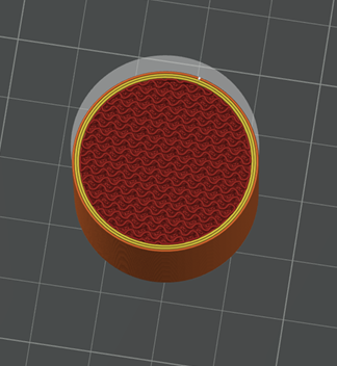
Test Protocol and Results
We compressed every specimen on a universal testing machine in the lab at Technische Hochschule Deggendorf, loading them from the top until the structure gave way. Five specimens per configuration, results averaged. At 40 % infill, grid was almost twice as strong as gyroid. We did not expect the gap to be that wide.
Grid won, consistently
For top-down compression — which is the most common loading direction for parts like spacers, brackets, and mounting blocks — grid infill was stronger than the other two at every single density level we tested. At 20% infill it was about 50% stronger than gyroid. At 80% infill it was still clearly ahead. Why? Because when you push straight down on a cylinder, the vertical grid walls align with the load and transfer it efficiently, like columns in a building. The gyroid's smooth curves redirect force along diagonal paths — elegant geometry, but not ideal for a straight vertical push.

More infill helps — but not as much as you'd think
Going from 20 % to 40 % infill nearly doubled the compressive strength. That's a big jump for a relatively small amount of extra material. But each step after that delivered less and less benefit. By the time you go from 80 % to 100 %, you're adding a lot of material and printing time for a much smaller strength gain.
The practical takeaway: somewhere in the 40–60 % range is often the sweet spot — meaningfully stronger than a light infill, without the waste of going near-solid.
More walls = more strength, especially at low infill
Adding a third or fourth wall perimeter made a noticeable difference, especially when the infill was sparse. At 20 % infill, going from 2 walls to 4 walls added about 22 % more compressive strength — just from thickening the outer shell, without touching the infill at all.
Think of it like this: when the inside is mostly air, the shell has to do more of the work. A thicker shell means more work capacity.
What This Means for Your Parts
If you are printing functional parts — things that will actually carry a load — here are the simple rules we'd take away from this research:
If your part is mainly being pushed or squeezed from one direction (think: a foot, a standoff, a clamp jaw), use grid infill at 40–60 % density with at least 3 walls.
If your part might get squeezed from different angles, or you genuinely don't know the load direction, gyroid is the safer bet for uniform strength.
Don't default to 100% infill thinking it's automatically the strongest option — a solid-shell specimen in our tests matched or beat 100% rectilinear at lower weight and less material.
Extra walls are cheap in terms of material and often more effective than cranking up infill percentage.
And if you're printing prototypes or non-structural parts? Any pattern at 15–20% is perfectly fine. Save the heavy settings for parts that need them.
At Gramm GmbH, we don’t rely on assumptions—we test and validate real performance. If your part needs to work in the real world, not just on screen, we can help you get the right balance between strength, weight, and cost.
👉 Reach out and let’s optimize your next design. Request a quotation now or start an inquiry!


Comments